How To Draw Bode Plot
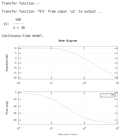
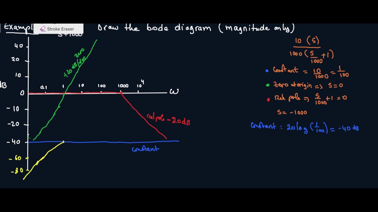
How To Draw Bode Plot - The plot can be used to interpret how the input affects the output in both magnitude and phase over frequency. Substitute, s = jω s = j ω in the above equation. Draw the bode diagram for each part. Web in this chapter, let us understand in detail how to construct (draw) bode plots. Web a bode plot is a graph used in control system engineering to determine the stability of a control system. Frequency response (18 of 56) bode plot: The plot displays the magnitude (in db). But we will cover the basics of how to bode plots for both magnitude and phase angle, explaining each step along the way. Click on the transfer function in the table below to jump to that example. One for magnitude and one for phas. The gain of a circuit, as a function of frequency. You can choose between these three options: Web to draw bode diagram there are four steps: In other words, what does a bode plot represent? this includes an animation. Combined with the gain margin and phase margin, a bode plot maps the frequency response of. Substitute, s = jω s = j ω in the above equation. Web this video describes the benefit of being able to approximate a bode plot by hand and explains what a bode plot looks like for a transfer function with either a pole or zero at the origin. A bode plot consists of two separate plots, one for magnitude Web going through how to draw the approximate bode plot for a system with one zero and two poles. Rewrite the transfer function in proper form. It will not cover complex topics. The table below summarizes what to do for each type of term in a bode plot. Choose the independent variable used in the transfer function. Bode plot is known to have a separate sketch for magnitude and phase angle. Web to use the bode plot calculator follow these steps: Separate the transfer function into its constituent parts. The plot displays the magnitude (in db) and phase (in degrees) of the system response as a function of frequency. Web this video illustrates the steps to draw bode plot for a given transfer function and also explains how to find gain margin (gm) and phase margin (pm) and comment on the. The plot can be used to interpret how the input affects the output in both magnitude and phase over frequency. Web introduction to bode plot. The table below summarizes what to do for each type of term in a bode plot. Web bode plots give engineers a way to visualize the effect of their circuit, in terms of voltage magnitude. In other words, what does a bode plot represent? this includes an animation. Web if you are only interested in a quick lesson on how to make bode diagrams, go to making plots. a matlab program to make piecewise linear bode plots is described in bodeplotgui. The gain is plotted in decibe. A bode plot consists of two separate plots,. Web this video describes the benefit of being able to approximate a bode plot by hand and explains what a bode plot looks like for a transfer function with either a pole or zero at the origin. Steps to construct bode plot. Web if you are only interested in a quick lesson on how to make bode diagrams, go to. Draw the overall bode diagram by adding up the results from part 3. Web to draw bode diagram there are four steps: Frequency response (18 of 56) bode plot: Web introduction to bode plot. Click on the transfer function in the table below to jump to that example. Separate the transfer function into its constituent parts. Draw the bode diagram for each part. Before analyzing the bode function. Represent the open loop transfer function in the standard time constant form. Web here in this article, we will see how the bode plot is sketched and later will explain the same with the help of an example. Web here in this article, we will see how the bode plot is sketched and later will explain the same with the help of an example. Web this video describes the benefit of being able to approximate a bode plot by hand and explains what a bode plot looks like for a transfer function with either a pole or zero. Steps to construct bode plot. Web lecture 17 exercise 102: Web the bode plot or the bode diagram consists of two plots −. Choose the type of bode plot you want to draw. Bode plot is known to have a separate sketch for magnitude and phase angle. Rules for construction of bode plots. Separate the transfer function into its constituent parts. Web here in this article, we will see how the bode plot is sketched and later will explain the same with the help of an example. Web to use the bode plot calculator follow these steps: But we will cover the basics of how to bode. Steps to construct bode plot. Web rules for drawing bode diagrams. Web to use the bode plot calculator follow these steps: You can choose between these three options: Click on the transfer function in the table below to jump to that example. But we will cover the basics of how to bode plots for both magnitude and phase angle, explaining each step along the way. Follow these rules while constructing a bode plot. Web in electrical engineering and control theory, a bode plot / ˈ b oʊ d i / is a graph of the frequency response of a system. One for magnitude and one for phas. Frequency response (18 of 56) bode plot: Several examples of the construction of bode plots are included here; Before analyzing the bode function. Combined with the gain margin and phase margin, a bode plot maps the frequency response of. Web lecture 17 exercise 102: S, while frequency is shown on. Web the bode plot or the bode diagram consists of two plots −.
simple method to draw bode plot3 YouTube

How to Draw Bode plot YouTube
Bode Plot Matlab How to do Bode Plot Matlab with examples?
Bode Plot Example Bode Diagram Example MATLAB Electrical Academia
A Beginner's Guide to Bode Plots

How To Draw Bode Plot

Drawing Bode Plot From Transfer Function SecondOrder Double Zero

how to draw bode plot in MATLAB Bode plot using MATLAB MATLAB

Bode Plot EXAMPLE YouTube
How to Draw a Bode Plot (Part 2) YouTube
Web Bode Plots Give Engineers A Way To Visualize The Effect Of Their Circuit, In Terms Of Voltage Magnitude And Phase Angle (Shift).
Web Introduction To Bode Plot.
The Gain Is Plotted In Decibe.
Separate The Transfer Function Into Its Constituent Parts.
Related Post: