Draw The Shear Diagram For The Beam
Draw The Shear Diagram For The Beam - Web construct shear and moment diagrams of this beam. 1) calculate support reactions 2) draw. Web understanding shear force and bending moment diagrams. Web shear force and bending moment diagrams are powerful graphical methods that are used to analyze a beam under loading. Welcome to beam calculator, our free version of the skyciv beam analysis software! K rd is a reduction factor to account for reduced ductility of grade 10.9. Web this video explains how to draw shear force diagram and bending moment diagram with easy steps for a simply supported beam loaded with a concentrated load. How to use skyciv beam calculator. Web the shear diagram helps engineers identify the points where the shear force is maximum or minimum, which is crucial for determining the beam’s strength and stability. Shear force and bending moment are examples of interanl forces that are induced in a structure when loads are applied to that structure. This page will walk you through what shear forces and bending moments are, why they are useful, the procedure for drawing the diagrams and some other keys aspects as well. Web in this post we’ll give you a thorough introduction to shear forces, bending moments and how to draw shear and moment diagrams with worked examples. Web drawing shear force and bending moment diagrams: 1) calculate support reactions 2) draw. Loading tends to cause failure in two main ways: They allow us to see where the maximum loads occur so that we can optimize the design to prevent failures and reduce the overall weight and cost of the structure. Web calculate the reactions at the supports of a beam, frame and truss. Web shear and moment equations and diagrams for beams. The shear and moment diagrams can then be drawn by plotting the shear and moment equations as a function of x. Try our free beam calculator today! Determine the placement distance a of the roller support so that the largest absolute value of the moment is a minimum. K rd is a reduction factor to account for reduced ductility of grade 10.9. Where f is the constant applied load and x is the distance along the beam. Check your work against the solution video: Determine all the. Web construct shear and moment diagrams of this beam. Web drawing shear force and bending moment diagrams: Web shear and moment diagrams are graphs which show the internal shear and bending moment plotted along the length of the beam. The shear and moment diagrams can then be drawn by plotting the shear and moment equations as a function of x.. The shear load and bending moment diagrams are constructed by integrating the distributed load to get the shear diagram (adding jumps at all point loads), and integrating the shear diagram to get the bending moment (adding jumps at all point couples). Web shear and moment equations and diagrams for beams. 1) calculate support reactions 2) draw. This page will walk. Web calculate the reactions at the supports of a beam, frame and truss. K r is a reduction factor for bolted lap connections; How to use skyciv beam calculator. Advanced physics questions and answers. Loading tends to cause failure in two main ways: Web draw the shearing force and bending moment diagrams for the cantilever beam subjected to a uniformly distributed load in its entire length, as shown in figure 4.5a. Φv f = ϕ * 0.62 * f uf * k r * k rd * (n n * a c + n x * a o). In each problem, let x. Web the moment equation would be: Web construct shear and moment diagrams of this beam. 1) calculate support reactions 2) draw. The shear load and bending moment diagrams are constructed by integrating the distributed load to get the shear diagram (adding jumps at all point loads), and integrating the shear diagram to get the bending moment (adding jumps at all. The shear and moment diagrams can then be drawn by plotting the shear and moment equations as a function of x. Web shear force and bending moment diagrams are powerful graphical methods that are used to analyze a beam under loading. Divide the beam (of length l) into n segments. Web draw the shearing force and bending moment diagrams for. Web calculate shear force diagrams. Shear and bending moment equations. Web drawing shear force and bending moment diagrams: Web in this post we’ll give you a thorough introduction to shear forces, bending moments and how to draw shear and moment diagrams with worked examples. In each problem, let x be the distance measured from left end of the beam. It is in static equilibrium. Web the as 4100 more specifically calculates bolt shear strength with the following equation: Web draw the shearing force and bending moment diagrams for the cantilever beam subjected to a uniformly distributed load in its entire length, as shown in figure 4.5a. The shear and moment diagrams can then be drawn by plotting the shear. In general the process goes like this: K rd is a reduction factor to account for reduced ductility of grade 10.9. Shear force and bending moment are examples of interanl forces that are induced in a structure when loads are applied to that structure. Φv f = ϕ * 0.62 * f uf * k r * k rd *. K r is a reduction factor for bolted lap connections; Your solution’s ready to go! This page will walk you through what shear forces and bending moments are, why they are useful, the procedure for drawing the diagrams and some other keys aspects as well. 1) calculate support reactions 2) draw. Determine all the reactions on the beam. It is in static equilibrium. Web construct shear and moment diagrams of this beam. In each problem, let x be the distance measured from left end of the beam. Web calculate shear force diagrams. F uf is the minimum tensile strength of the bolt; Web the moment equation would be: Web the first step in calculating these quantities and their spatial variation consists of constructing shear and bending moment diagrams, \(v(x)\) and \(m(x)\), which are the internal shearing forces and bending moments induced in. Web draw the shearing force and bending moment diagrams for the cantilever beam subjected to a uniformly distributed load in its entire length, as shown in figure 4.5a. A moment diagram shows the variation of the bending moment along the length of. Try our free beam calculator today! Shear force and bending moment are examples of interanl forces that are induced in a structure when loads are applied to that structure.
Solved Draw the shear diagram for the beam. Follow the

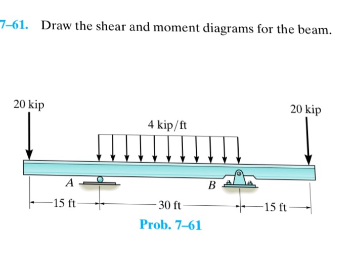
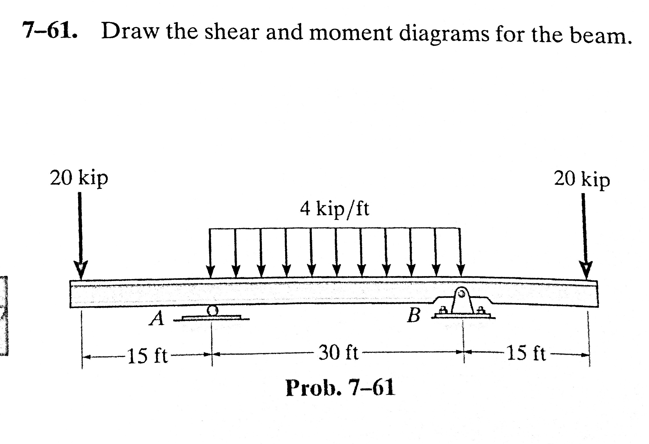
Draw the shear and moment diagrams for the beam.

Draw The Shear Diagram For The Beam Set P 800 Lb A 5 Ft L 12 Ft Free

Beam Shear And Moment Diagrams

Learn How To Draw Shear Force And Bending Moment Diagrams Engineering

Solved Draw the shear and moment diagrams for the beam.

Brief Information About Shear Force And Bending Moment Diagrams
Beam Shear And Moment Diagrams
Solved Draw the shear diagram for the beam. Follow the
Draw The Shear Diagram For The Beam Wiring Site Resource
20 Kn 40 Kn/M Cl 150 Kn M 8 M 3 M Prob.
Loading Tends To Cause Failure In Two Main Ways:
We Go Through Breaking A Beam Into Segments, And Then We Learn About The Relationships Between Shear Force And.
Draw The Shear And Moment Diagrams For The Beam.
Related Post: